01 / PROJECT DOCUMENTATION
YouTube ↗Explorer in three minutes
The project process, from initial exploration to the integrated prototype.
Explorer asks how a forest-monitoring drone could remain useful after its motors stop. I developed a flight-capable prototype that combines active perching, depth sensing, embedded control and experimental solar charging.
Explore the process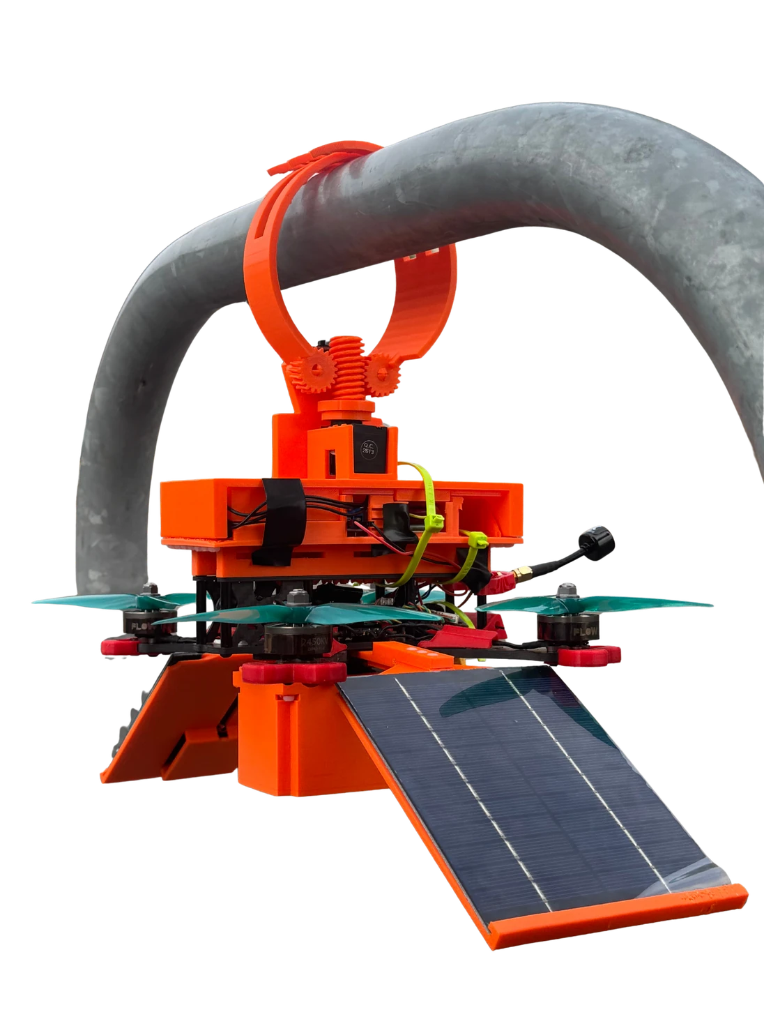
Individual MSc major project · research, design, fabrication, electronics, software and testing
SolidWorks · FDM printing · ESP32-S3 · Dynamixel · ToF sensing
A monitoring aircraft consumes energy simply staying in the air. Explorer investigates a different operating cycle: travel to a useful location, attach to a branch, stop propulsion and continue collecting environmental information.
The wider vision is a distributed monitoring network. The major project focused on its first practical unit: one aircraft that could fly, retain its own mass on a perch, sense its surroundings and record data.
Use flight to reach a monitoring position.
Transfer support from the rotors to a physical perch.
Continue sensing and explore solar-assisted energy recovery.
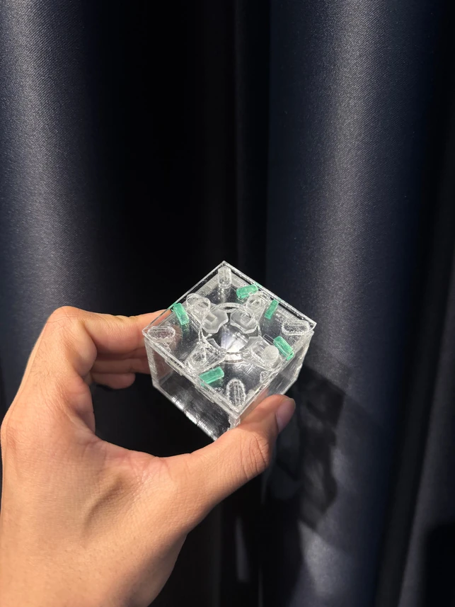
My first mechanism used a wide lateral arrangement with several moving relationships. Printing and assembly revealed its cost in width, mass, alignment and interference. A smaller direct-gear design reduced the footprint, but could back-drive under load.
I moved to a worm-driven architecture and iterated tooth geometry, shaft support, hook clearance and mounting. The intention was to retain a perch without depending on continuous servo holding torque. Physical parts made the problems visible far earlier than a finished render could.
The carbon frame carries flight loads; custom printed parts locate the actuator, power hardware, electronics and battery around it. The packaging had to respect the centre of gravity, propeller sweep, cable routes and access for assembly.
Repeated fits exposed details that looked acceptable in CAD: blocked screws, weak snap features, battery straps, connector clearance and wiring space. I developed the prototype around parts that could actually be assembled and serviced, then consolidated the bench wiring into the aircraft.
Separate the structural frame from component-specific housings.
Leave space to connect, fasten, remove and adjust real parts.
Evaluate component placement in flight and on the perch.
Reliable Dynamixel communication and repeatable position control came first. That feedback loop let me change hook geometry and recalibrate movement without redesigning the electronics each time.
The ESP32-S3 acquired frames from the VL53L8CX 8 × 8 Time-of-Flight sensor. Live visualisation helped interpret depth data during development; onboard logging allowed sessions to be replayed after testing. The experimental solar architecture was integrated as a separate energy-recovery investigation.
Flight testing confirmed stable, controllable operation with the integrated hardware. Controlled low-height retention tests demonstrated hook actuation, support of the vehicle’s mass and release. Manual in-flight alignment with a branch was not successfully completed.
A subsequent piloting error caused a low-height impact and damaged the hooks and solar-panel housing. That failure made impact protection and field robustness explicit requirements for the next iteration.
Controllable flight, RC actuation, retention, release and depth logging.
Hook and solar mounts need to survive handling and impact.
Closed-loop approach, repeatable capture and environmental endurance.
The final product vision translates the functional prototype into a more integrated aircraft. It considers fewer assemblies, protected electronics, lighter energy hardware and replaceable service modules.
Accessible hobby electronics and commercial panels accelerated experimentation. A field-ready platform would need a stronger energy-to-mass ratio, environmental protection and much longer reliability testing.
The project process, from initial exploration to the integrated prototype.
Field testing and the impact that informed the next iteration.
The prototype takes to the air.
Watching depth data as it arrives from the sensor.
The visualisation environment developed for the sensing workflow.
Establishing communication with the actuator.
Turning a control signal into physical movement.
A closer look at the transmission in motion.
An earlier mechanism iteration, captured during development.
The strongest result is the integration of mechanics, electronics and testing in a functioning platform, and a precise understanding of what remains to be solved.
Major-project discovery folio; final 195-page CW2 folio, particularly mechanism development and pages 169–193; updated portfolio, pages 3–9.
Small scale. Precise decisions.