An intuitive connection, at 50 millimetres.
A small object with demanding rules: connect two acrylic cubes across two faces, align their edges and make the interaction understandable, without magnets. Each prototype turned an abstract mechanism into a more precise physical experience.
Explore the process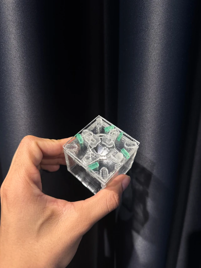
Mechanism design, CAD, laser-cut prototyping and manufacturing development
3 mm acrylic · laser cutting · CAD/CAM · CNC · vacuum forming
A connection should explain itself.
The brief was more than making two cubes attach. The faces needed to align, the connection needed to hold, and the action needed to be discoverable without a demonstration. The material and scale made every small tolerance visible.
I evaluated concepts through five questions: is the action intuitive, does it secure, do the edges align, is there tactile feedback, and can the parts move reliably?
Discover
Geometry and engraving suggest the intended action.
Connect
The movement guides the two faces into alignment.
Confirm
A stable locked position feels different from an incomplete connection.
Twelve blades were not the answer.
Early insert-and-twist tests explored friction and alignment. An iris-inspired mechanism made the difficulty tangible: rails, pins and blades were too small, and the top and bottom paths did not agree.
I reduced the blade count and replaced curved movement paths with simpler straight slots. Even then, fine pins and layered friction resisted smooth motion. Each laser-cut build narrowed the problem: fewer parts, larger features, better support and a clearer movement path.
Small adjustments. A more certain lock.
The selected design moves the blades inward to retain the mating part and outward to release it. A support layer stabilises the blades; spacer geometry leaves the clearance they need to move.
Repeated cutting established an approximately 0.2 mm kerf adjustment for this material and setup. Further changes reduced pin friction, corrected the mating-part stack and shortened interfering blades. The result balances smooth movement with a stable connection.
Manufacturing changed the form, too.
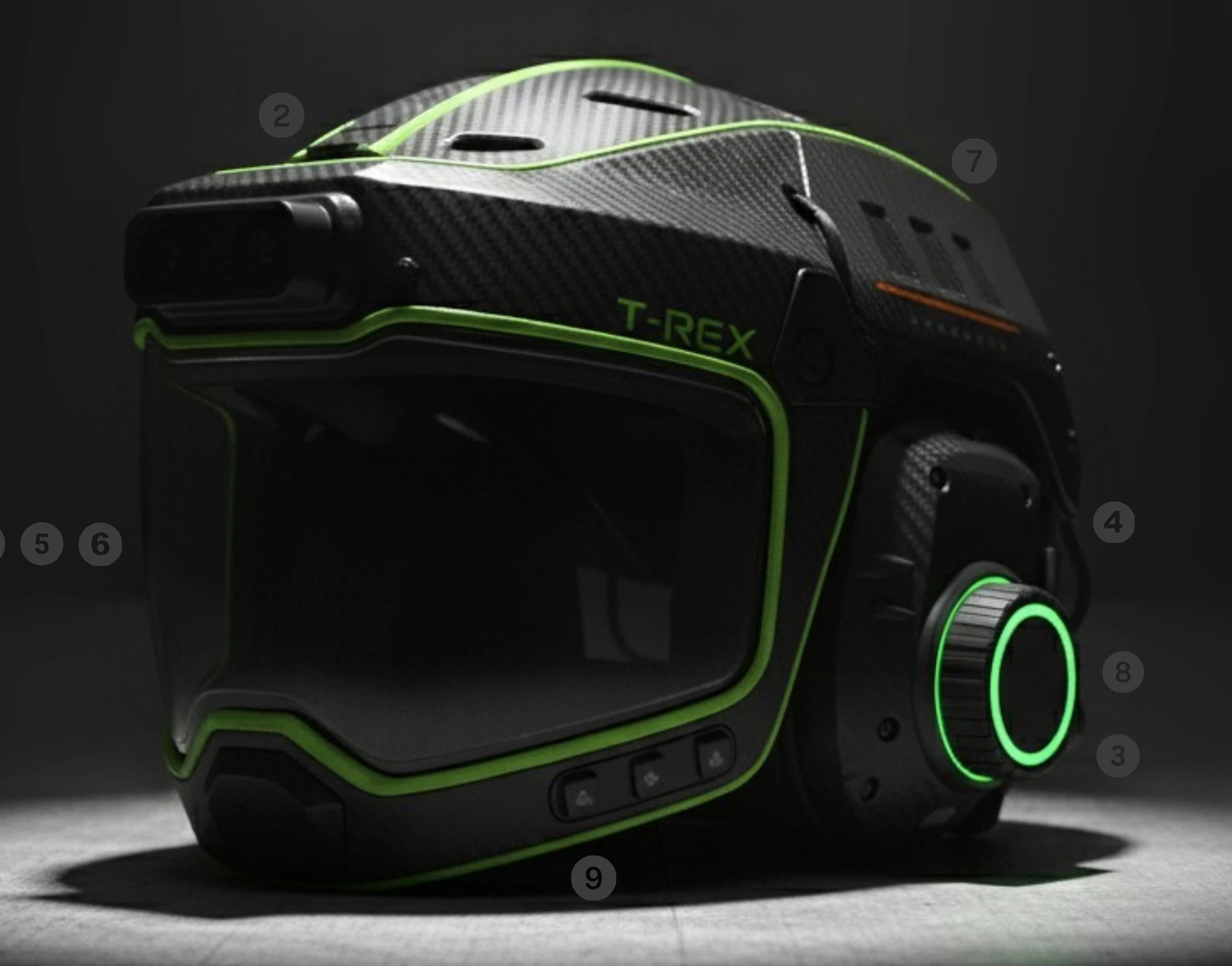
The accompanying CNC and vacuum-forming work extended the same principle: manufacturing is part of design. A racing-car-inspired mould needed modified wings and vents, softened transitions and enough clearance for the plastic to form and release.
I used at least 3° of draft and 3 mm fillets, removed undercuts and revised the machining strategy. Early chatter, melting and unnecessary air cutting led to feed, step-over and toolpath changes. The documented stay-down strategy removed ten minutes of non-cutting movement.
3°
Minimum draft considered for mould release.
3 mm
Minimum fillet used to soften the form.
0.01 mm
Toolpath smoothing tolerance in the final CAM strategy.
Precision comes from making.
This project demonstrates how I use physical iteration to resolve interaction, tolerance and manufacturing together.
What the project delivered
- Repeatable mechanical cube connection
- Reduced blade count and simpler paths
- Documented tolerance and clearance strategy
- CNC-machined moulds and vacuum-formed outcomes
Where I would take it next
- Longer cycle testing for wear and friction
- Broader usability testing of discovery and feedback
- Verify tolerances across other machines and materials
Digital fabrication presentation, pages 1–10; updated portfolio, pages 10–12.
Designed around demanding work.